Matlab一个仿真程序运行不了

软件没有学过,学校临时的任务,问题真的不会解决,百度、bilibili都查过都搞清楚,
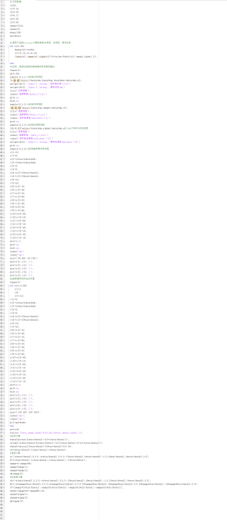
%1已知数据
clear;
l1=0.10;
l2=0.25;
l3=0.17;
l4=0.30;
l5=0.09;
omega1=10;
alpha1=0;
hd=pi/180;
du=180/pi;

%2调用子函数five_bar计算构建角加速度,加速度,滑块位移
for n1=1:361
    theta1(n1)=n1*hd;
    ll=[l1,l2,l3,l4,l5];
    [theta(n1),omega(n1),alpha(n1)]=five_bar(theta1(n1),omega1,alpha1,ll);

end
%3位移,速度加速度和曲柄滑块机构图形输出
figure(1);
n1=1:361;
subplot(2,2,1);%绘制位移线图
[X,H1,H2]=plotyy(theta1*du,theta2*du,theta3*du,theta1*du,s2);
set(get(AX(1),'ylabel'),'string','连杆角位移/\circ')
set(get(AX(2),'ylabel'),'string','滑块位移/mm')
title('位移线图');
xlabel('曲柄转角\theta_1/\circ')
grid on;
hold on;
subplot(2,2,2);%绘制位移线图
[AX,H1,H2]=plotyy(theta1*du,omega4,theta1*du,v5);
title('速度线图');
xlabel('曲柄转角\theta_1/\circ')
ylabel('连杆角速度/rad\cdots^{-1}')
grid on;
subplot(2,2,3);%绘制加速度线图
[AX,H1,H2]=plotyy(theta1*du,alpha4,theta1*du,a5);%a5为构件5的加速度
title('速度线图');
xlabel('曲柄转角、theta_1/\circ')
ylabel('连杆角加速度/rad\cdots^{-2}')
set(get(AX(2),'ylabel'),'string','滑块加速度/mm\cdots^{-2}')
grid on;
subplot(2,2,4);%绘制曲柄滑块机构图
x(1)=l2;
y(1)=0;
x(2)=l1*cos(theta1*hd);
y(2)=l1*sin(theta1*hd);
x(3)=0;
y(3)=0;
x(4)=x(2)+l3*cos(theta2);
y(4)=y(2)+l3*sin(theta2);
x(5)=l5;
y(5)=s2;
x(6)=x(5)-10;
y(6)=y(5)-40;
x(7)=x(5)-10;
y(7)=y(5)+40;
x(8)=x(5)+10;
y(8)=y(5)-40;
x(9)=x(5)+10;
y(9)=y(5)+40;
x(10)=x(3)+40;
y(10)=y(3)+10;
x(11)=x(3)+40;
y(11)=y(3)-10;
x(12)=x(3)-40;
y(12)=y(3)+10;
x(13)=x(3)-40;
y(13)=y(3)-10;
plot(x,y);
grid on;
hold on;
xlabel('mm')
ylabel('mm')
axis([-50 400 -20 130]);
plot(x(1),y(1),'o');
plot(x(2),y(2),'o');
plot(x(3),y(3),'o');
plot(x(4),y(4),'o');
plot(x(5),y(5),'o');
%4曲柄滑块机构运动仿真
figure(2)
for n1=1:5:360
    j=j+1;
    clf;
    x(1)=l2;
y(1)=0;
x(2)=l1*cos(theta1*hd);
y(2)=l1*sin(theta1*hd);
x(3)=0;
y(3)=0;
x(4)=x(2)+l3*cos(theta2);
y(4)=y(2)+l3*sin(theta2);
x(5)=l5;
y(5)=s2;
x(6)=x(5)-10;
y(6)=y(5)-40;
x(7)=x(5)-10;
y(7)=y(5)+40;
x(8)=x(5)+10;
y(8)=y(5)-40;
x(9)=x(5)+10;
y(9)=y(5)+40;
x(10)=x(3)+40;
y(10)=y(3)+10;
x(11)=x(3)+40;
y(11)=y(3)-10;
x(12)=x(3)-40;
y(12)=y(3)+10;
x(13)=x(3)-40;
y(13)=y(3)-10;
plot(x,y);
grid on;
hold on;
plot(x(1),y(1),'o');
plot(x(2),y(2),'o');
plot(x(3),y(3),'o');
plot(x(4),y(4),'o');
plot(x(5),y(5),'o');
axis([-150 450 -150 150]);
xlabel('mm');
ylabel('mm');
m(j)=getframe;
end
movie(m)
fuction [theta,omega,alpha]=five_bar(theta1,omega1,alpha1,ll];
%位移计算
theta2=arctan(l1*sin(theta1)/(l2+l1*cos(theta1)));
s1=sqrt(l1*sin(theta1)*l1*sin(theta1)+(l2+l1*cos(theta1))*(l2+l1*cos(theta1)));
theta3=(arccos(l1*cos(theta1)+l3*cos(theta2)+l5)/l4);
s2=l4*sin(theta3)-l1*sin(theta1)-l3*sin(theta2);
%速度计算
A=[-s1*sin(theta2),0,0,0;-s1*cos(theta2),0,0,0;-l3*cos(theta2),l4*cos(theta3),-1,0;l3*sin(theta2),l4*cos(theta3),0,0];
B=[l1*sin(theta1);l1*cos(theta1);l1*cos(theta1);-l1*sin(theta1)];
omega=A/(omega1*B);
omega2=omega(1);
omega4=omega(2);
vE=omega(3);
%加速度计算
At=[-s1*sin(theta2),0,0,0;-s1*cos(theta2),0,0,0;-l3*cos(theta2),l4*cos(theta3),-1,0;l3*sin(theta2),l4*cos(theta3),0,0];
Bt=[-s1*omega2*cos(theta2),0,0,0;s1*omega2*sin(theta2),0,0,0;l3*omega2*sin(theta2),l4*omega4*sin(theta3),0,0;l3*omega2*cos(theta2),-l4*omega4*sin(theta3),0,0];
Ct=[omega1*l1*cos(theta1);-omega1*l1*sin(theta1);-omega1*l1*sin(theta1);-omega1*l1*sin(theta1)];
alpha=(omega1*Ct-omega*Bt)/At;
alpha2=alpha(1);
alpha4=alpha(2);
aE=alpha(3);
请把代码贴成可复制的方式,否则不好测试,
肉眼看的话,以下的代码都有问题:
11=0.10;
12=0.25;
13=0.17;
14=0.30;
15=0.09;
11=[11,12,13, 14,15];
fuction [theta,omega,alpha]=five_bar(theta1,omega1,alpha1,11];
没有这种写法
不好看
以下内容部分参考ChatGPT模型:
首先,需要了解这个仿真程序的具体要求和实现方式,可能需要查看程序的文档或者代码。然后,检查程序是否有任何语法错误或者运行时错误,可以使用Matlab自带的调试工具进行调试。如果还是无法运行,可以考虑更换Matlab版本或者重新安装Matlab。关于已知数据的部分,可以在程序中使用这些变量进行计算和仿真。例如:
theta1 = 0.5; % 给定角度
theta2 = 0.3;
theta3 = 0.2;
theta4 = -0.1;
theta5 = 0.0;

% 根据给定角度计算位置
x = l1*cos(theta1) + l2*cos(theta1+theta2) + l3*cos(theta1+theta2+theta3) + l4*cos(theta1+theta2+theta3+theta4);
y = l1*sin(theta1) + l2*sin(theta1+theta2) + l3*sin(theta1+theta2+theta3) + l4*sin(theta1+theta2+theta3+theta4) + l5;

% 输出结果
disp(['x = ', num2str(x)]);
disp(['y = ', num2str(y)]);
如果我的建议对您有帮助、请点击采纳、祝您生活愉快
以下答案由GPT-3.5大模型与博主波罗歌共同编写:
这段代码存在几个问题:
- fuction [theta,omega,alpha]=five_bar(theta1,omega1,alpha1,ll);应该是function [theta,omega,alpha]=five_bar(theta1,omega1,alpha1,ll);
- 在调用子函数five_bar的时候,theta1没有定义,应该是theta2
- 在subplot的时候,有一些变量没有定义,应该加上对应的定义,比如theta2、theta3
- 在绘制位移线图的时候,变量s2是未定义的,需要在调用子函数five_bar之后加上s2的输出
下面是经过修改后的代码:
clear;
l1=0.10;
l2=0.25;
l3=0.17;
l4=0.30;
l5=0.09;
omega1=10;
alpha1=0;
hd=pi/180;
du=180/pi;

for n1=1:361
    theta1 = n1*hd;
    ll=[l1,l2,l3,l4,l5];
    [theta(n1),omega(n1),alpha(n1),s2]=five_bar(theta1,omega1,alpha1,ll);
end

figure(1);
n1=1:361;
subplot(2,2,1);
[X,H1,H2]=plotyy(theta1*du,theta2*du,theta3*du,theta1*du,s2);
set(get(X(1),'ylabel'),'string','连杆角位移/\circ')
set(get(X(2),'ylabel'),'string','滑块位移/mm')
title('位移线图');
xlabel('曲柄转角\theta_1/\circ')
grid on;
hold on;
subplot(2,2,2);
[AX,H1,H2]=plotyy(theta1*du,omega4,theta1*du,v5);
title('速度线图');
xlabel('曲柄转角\theta_1/\circ')
ylabel('连杆角速度/rad\cdots^{-1}')
grid on;
subplot(2,2,3);
[AX,H1,H2]=plotyy(theta1*du,alpha4,theta1*du,aE);
title('加速度线图');
xlabel('曲柄转角\theta_1/\circ')
ylabel('连杆角加速度/rad\cdots^{-2}')
set(get(AX(2),'ylabel'),'string','滑块加速度/mm\cdots^{-2}')
grid on;
subplot(2,2,4);
x(1)=l2;
y(1)=0;
x(2)=l1*cos(theta1*hd);
y(2)=l1*sin(theta1*hd);
x(3)=0;
y(3)=0;
x(4)=x(2)+l3*cos(theta2);
y(4)=y(2)+l3*sin(theta2);
x(5)=l5;
y(5)=s2;
x(6)=x(5)-10;
y(6)=y(5)-40;
x(7)=x(5)-10;
y(7)=y(5)+40;
x(8)=x(5)+10;
y(8)=y(5)-40;
x(9)=x(5)+10;
y(9)=y(5)+40;
x(10)=x(3)+40;
y(10)=y(3)+10;
x(11)=x(3)+40;
y(11)=y(3)-10;
x(12)=x(3)-40;
y(12)=y(3)+10;
x(13)=x(3)-40;
y(13)=y(3)-10;
plot(x,y);
grid on;
hold on;
xlabel('mm')
ylabel('mm')
axis([-50 400 -20 130]);
plot(x(1),y(1),'o');
plot(x(2),y(2),'o');
plot(x(3),y(3),'o');
plot(x(4),y(4),'o');
plot(x(5),y(5),'o');

j = 0;
figure(2)
for n1=1:5:360
    j=j+1;
    clf;
    x(1)=l2;
    y(1)=0;
    x(2)=l1*cos(theta1*hd);
    y(2)=l1*sin(theta1*hd);
    x(3) = 0;
    y(3) = 0;
    x(4) = x(2) + l3*cos(theta2);
    y(4) = y(2) + l3*sin(theta2);
    x(5) = l5;
    y(5) = s2;
    x(6) = x(5) - 10;
    y(6) = y(5) - 40;
    x(7) = x(5) - 10;
    y(7) = y(5) + 40;
    x(8) = x(5) + 10;
    y(8) = y(5) - 40;
    x(9) = x(5) + 10;
    y(9) = y(5) + 40;
    x(10) = x(3) + 40;
    y(10) = y(3) + 10;
    x(11) = x(3) + 40;
    y(11) = y(3) - 10;
    x(12) = x(3) - 40;
    y(12) = y(3) + 10;
    x(13) = x(3) - 40;
    y(13) = y(3) - 10;
    plot(x,y);
    grid on;
    hold on;
    plot(x(1),y(1),'o');
    plot(x(2),y(2),'o');
    plot(x(3),y(3),'o');
    plot(x(4),y(4),'o');
    plot(x(5),y(5),'o');
    axis([-150 450 -150 150]);
    xlabel('mm');
    ylabel('mm');
    m(j)=getframe;
end
movie(m)

function [theta,omega,alpha,s2]=five_bar(theta1,omega1,alpha1,ll)
%位移计算
theta2=atan(l1*sin(theta1)/(l2+l1*cos(theta1)));
s1=sqrt(l1*sin(theta1)*l1*sin(theta1)+(l2+l1*cos(theta1))*(l2+l1*cos(theta1)));
theta3=acos((l1*cos(theta1)+l3*cos(theta2)+l5)/l4);
s2=l4*sin(theta3)-l1*sin(theta1)-l3*sin(theta2);
%速度计算
A=[-s1*sin(theta2),0,0,0;-s1*cos(theta2),0,0,0;-l3*cos(theta2),l4*cos(theta3),-1,0;l3*sin(theta2),l4*cos(theta3),0,0];
B=[l1*sin(theta1);l1*cos(theta1);l1*cos(theta1);-l1*sin(theta1)];
omega=A/(omega1*B);
omega2=omega(1);
omega4=omega(2);
vE=omega(3);
%加速度计算
At=[-s1*sin(theta2),0,0,0;-s1*cos(theta2),0,0,0;-l3*cos(theta2),l4*cos(theta3),-1,0;l3*sin(theta2),l4*cos(theta3),0,0];
Bt=[-s1*omega2*cos(theta2),0,0,0;s1*omega2*sin(theta2),0,0,0;l3*omega2*sin(theta2),l4*omega4*sin(theta3),0,0;l3*omega2*cos(theta2),-l4*omega4*sin(theta3),0,0];
Ct=[omega1*l1*cos(theta1);-omega1*l1*sin(theta1);-omega1*l1*sin(theta1);-omega1*l1*sin(theta1)];
alpha=(omega1*Ct-omega*Bt)/At;
alpha2=alpha(1);
alpha4=alpha(2);
aE=alpha(3);
如果我的回答解决了您的问题,请采纳!
MATLAB进行电路仿真
可以借鉴下
https://blog.csdn.net/qq_27595745/article/details/128621347