matlab与信号处理系统设计实验
已知输入信号为混有噪声的信号
x(t)=sin(250πt)+cos(500πt)+cos(700πt)
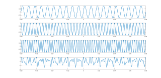
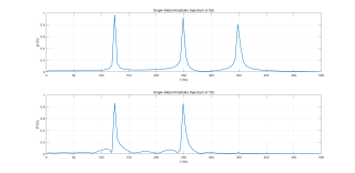
①画出输入信号时域波形和频谱图,并指出其包含的频率成分(以Hz为单位);
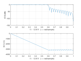
②假定输入信号的中间频率成分为噪声信号,请问应如何设计数字滤波器处理该混合信号,给出合理的设计指标并说明理由,画出滤波器的频响特性:要求两种以上的实现方案。
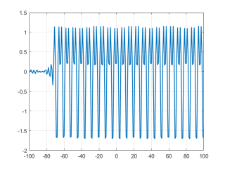
③用(2)中设计的滤波器完成滤波并验证设计方案,画出滤波器输出信号时域波形和频谱图。
clc,clear,close all;
t = -0.08:0.0001:0.08;
n = -100:100;
L = length(n);
fs = 1000;
x0 = sin(2*pi*125.*n/fs);  %时域采样后的信号t=nT=n/fs
x1 = cos(2*pi*250.*n/fs);
x2 = cos(2*pi*350.*n/fs);
x3 = x0 + x1 + x2;
%时域信号
figure(1)
subplot(411)
plot(t,sin(2*pi*125.*t),"LineWidth",1.5)
grid on
subplot(412)
plot(t,cos(2*pi*250.*t),"LineWidth",1.5)
grid on
subplot(413)
plot(t,cos(2*pi*350.*t),"LineWidth",1.5)
grid on
subplot(414)
plot(t,sin(2*pi*125.*t)+cos(2*pi*250.*t)+cos(2*pi*350.*t),"LineWidth",1.5)
grid on
%滤波器设计
wn = 3/5;  %截止频率wn为3/5pi(300Hz),wn = 2pi*f/fs
N = 60;  %阶数选择
hn = fir1(N-1,wn,boxcar(N));  %10阶FIR低通滤波器
figure(2)
freqz(hn,1);
figure(3)
y = fftfilt(hn,x3);  %经过FIR滤波器后得到的信号
plot(n,y,"LineWidth",1.5)
grid on
%频谱分析
X = fft(x3); %未滤波前的频谱
p2 = abs(X/L);
p1 = p2(1:L/2+1);
p1(2:end-1) = 2*p1(2:end-1);
Y = fft(y);  %输出信号的fft
P2 = abs(Y/L);
P1 = P2(1:L/2+1);
P1(2:end-1) = 2*P1(2:end-1);
f = fs*(0:(L/2))/L;
figure(4)
subplot(211)
plot(f,p1,"LineWidth",1.5)
title('Single-Sided Amplitude Spectrum of X(t)')
xlabel('f (Hz)')
ylabel('|p1(f)|')
grid on
subplot(212)
plot(f,P1,"LineWidth",1.5)
title('Single-Sided Amplitude Spectrum of Y(t)')
xlabel('f (Hz)')
ylabel('|P1(f)|')
grid on
时域波形:分别为125(2pi*125=250pi)、250和350Hz的余弦信号
截止频率为300Hz的fir低通滤波器:
滤波前和滤波后的频谱:
滤波后的时域信号:
PS:问答VIP年卡 【限时加赠:IT技术图书免费领】,了解详情>>> https://vip.csdn.net/askvip?utm_source=1146287632